Tel. 01538 756800
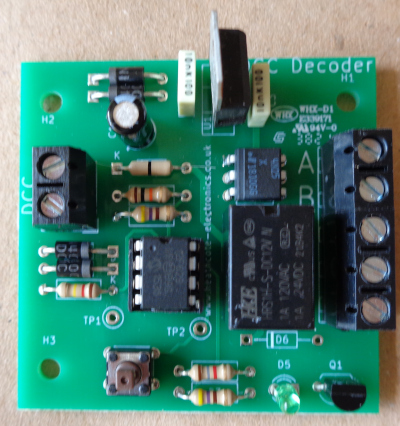
DCC Accessory Decoder-1

The DCC Accessory Decoder-1 works exactly as a points decoder but instead of switching points it operates lights, lamps, electric motors, sound boards, signals and our other boards such as the Single and Dual Servo controllers. This allows DCC to control movements such as semaphore signals, opening gates and barriers, uncouplers, cranes, swing bridges, doors etc. It connects to the track with 2 wires this provides the DCC Accessory Decoder-1 with power and DCC commands. It is very simple and flexible to use as it only has one channel so can be located close to the unit it is controlling. The outputs are electrically isolated from the DCC supply making it easy to control items powered by a different power supply.
It operates the equivalent of a SPDT switch (changeover) which can also be used as an on/off switch. The DCC Accessory Decoder-1 has a second output designed to activate our other boards. The DCC Accessory decoder-1 will work with any DCC system that has the capability to operate point motors. The DCC Accessory Decoder responds to all points addresses (approx 2048 addresses)
Setting the address.
The DCC Accessory Decoder learns its address. When its push button is pressed it looks for the first point switching command and this becomes its address.
First connect the DCC terminals to the track with 2 wires.
Press the push button on the DCC Accessory Decoder-1. After 2 seconds the green LED will flash. Set your DCC Controller to the accessory address (points address) you want to program for example 17. (This is the identical procedure to operating your points by DCC)
Press the move the points command on your DCC controller.
The Green LED will stop flashing and either light continuously or extinguish and the address just sent will be remembered and become the address of the DCC Accessory Decoder-1.
Send the command for the points to move to their other position. If the green LED is lit it will now extinguish and if it was unlit it will now light.
The green LED indicates whether or not the DCC Accessory Decoder-1 outputs are switched on or off. The green LED lights when the outputs are activated. Both the address and state of the outputs will be remembered when the power is switched off.
This process can be repeated if you wish to change the DCC Accessory Decoder1s address in the future.
Outputs
Relay output

This functions exactly as a SPDT switch. The contacts are electrically separate from the DCC wiring so it can be used exactly as a switch.
Terminals C and E are connected when the green LED is lit. Terminals C and D are connected when the green LED is extinguished.
The relay output can be used, for example, to switch lights, sounds or electrical motors on and off. or to operate the Dapol semaphore junction signals.
Opto isolator output

The opto isolator output can be used instead of a switch or an IRDOT-1 to provide DCC Control for our other products. The opto isolator output provides an isolated output for switching devices connected to a different power supply. For example it could be connected to our Servo Control boards. (The output is identical to terminal 2 of the IRDOT-1.) Connect the negative supply terminal (generally called 0V on our boards) to terminal B on the DCC Accessory Decoder-1. Connect the input terminal (for example S on the Servo Control Board) to terminal A.
Another use of the optoisolator output is to operate the OI terminal on our MAS Sequencer RI and IRDASC RI boards. On these boards the OI terminal lights the feather on signals provided the signal is not at red. If the DCC Accessory decoder-1 is programmed with the same address as the point associated with the signal and the opto isolator output is connected to the OI terminal then the signal feather will change when the point operates.
DCC operation of points with servos
The opto isolator output can be connected to the Single Servo Controller and the relay output can be used to switch the points frog.
Operating Dapol Junction Semaphore signals

The more recent Dapol Semaphore signals use built in Servos to activate the signal arms. These are designed for operation with a SPDT switch. This exactly matches the relay contacts.
Dimensions of DCC Accessory Decoder-1:
Length 53 mm 2 1/10 inches
Width 50 mm 2 inches