Tel.
01538 756800
SA2 and SA2-S
The SA2 is a single line shuttle with a siding at one end to allow two trains to run alternately along a single track line with sidings at each end. The SA2-S works identically to the SA2 but has additional controls for four starter signals. The SA2 and SA2-S gives a gradual adjustable braking and acceleration, an adjustable speed and adjustable wait time at the ends of the line. It has controls on the board to operate the points for the sidings. The standard versions operate solenoid point motors but we can also supply SA2 and SA2-S to operate slow motion point motors.
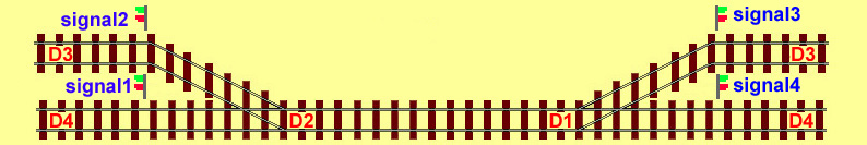
The SA2-S operates as follows. Assume both trains start at the left-hand sidings. There is an adjustable delay, the points change for the train standing over D3, another short delay. Signal2 clears (changes to green) for the train. There is a further short delay. The first train accelerates away to the right. On being detected at D1 the train gradually slows to an adjustable minimum speed and stops when detected at D3. After an adjustable delay time the points change to the D4 line then signal 2 clearsand the second train accelerates to the right, braking on reaching D1 and stopping at D4.
Both trains are now at the right.
After an adjustable delay the point changes then signal 3 clears for the train standing over D3 (at the right). This train accelerates repeats the journey to D3 on the left braking on reaching D2. Finally after a further adjustable delay the points change to the D4 line then signal 4 clears and the train returns to the left D4 accelerating and braking as previous.
Both trains are now back at the left and the sequence continues from the beginning.
Note that as you move through this sequence there will be either no one or two trains in the station.
After changing to clear the signal will return to danger when an internal timer finishes timing, however if the train reaches the start slowing position the signal will return to danger at this point.
Detectors
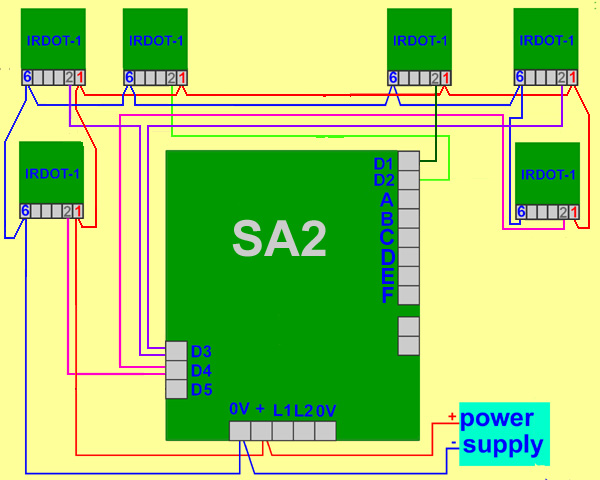
In addition to the SA2-S board you require 6 train detectors These tell the SA2 where the train is so that it can slow or stop the train. Either IRDOT-1s or reed switches may be used as train detectors. Reed switches require magnets be fitted to the engine or rolling stock. You also require a power supply of 12 to 16 volts and a source of power for the point motor.
The train detectors are labelled D1, D2, D3, and D4. These numbers refer to the terminals on the SA9 to which the detectors are wired. Terminal D1 makes left to right trains gradually brake and terminal D2 makes right to left trains brake. D3 D4 and D5 (on the single track end) make the SA9-S stop the train. One or both of the slowing detectors may be omitted. This will result in a sudden rather than gradual stop.
Point operation

The standard SA2 and SA2-S operates solenoid point motors such as Peco, Seep and Hornby. There are two sets of contacts on the SA2-S board. These contacts close for a second to operate the point. The wiring is electrically identical to wiring a point motor operated by two push button switches.
If requested, versions of the boards suitable for a slow motion point motor or a servo motor can be supplied.
Signal operation (SA2-S)
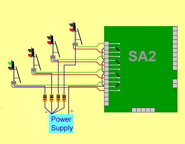
The appropriate signal changes to clear (green) just before the train departs, a few seconds after the train departing the signal returns to danger (red), if the signal has not returned to red by the time the train reaches the slowing detector it will return to red at this point.
Signal operation uses contacts built into the SA2-S board, allowing any type of two aspect colour light signal to be operated. These contacts shown in white have no electrical connection to the SA2-S board. Wiring to them is identical electrically to wiring to spdt (single pole double throw) also called changeover switches.
Semaphore signals can also be operated. Some options to are:- Use the contacts to switch the dual servo motor controller and use a servo motor to control the semaphore signals movement. Operate the semaphore signal by memory wire, using the closure of the contacts to apply current to the memory wire. Use a slow motion point motor wired via the contacts with an AC supply and diodes to give a change in DC polarity to the point motor. See the circuit for Kato point motors. We also have a version of the SA2-S the SA2-SD for operating Dapol semaphore signals.
Adjustment Controls
No controller is required. The following adjustments are provided:- maximum speed, minimum speed, acceleration/braking, waiting time. Each adjustment is made with a pot fitted on the SA2-S board. The pots are adjusted by rotating with a small screwdriver.

Maximum speed: This controls the maximum speed the train travels at.
Minimum speed: After the train has gradually slowed (braked) it continues at the minimum speed until until reaching the stop detector. The minimum speed is adjusted to the slowest speed that the train will move reliably at.The purpose of the minimum speed is to ensure the train will stop in the desired place preventing the potential problem of the train stopping before it reaches the end of the platform.
Acceleration/braking: This allows the train to gradually increase or decrease speed in a realistic way. It is adjusted by rotating the pot. The pot adjusts the rate of braking and of acceleration. Turned one way the train accelerates and brakes more slowly. Turned the other way the train accelerates and brakes more quickly.
Waiting time: This is the time the train waits at each end before returning. The waiting time can be adjusted between 10 and 150 seconds.
Current rating: All boards are fitted with an overload cutout. This operates at 1 amp. Units can be modified to supply a higher current for use with G scale etc. We are happy to quote for this modification.
Power Supply
The SA2 and SA2-S can be powered from any supply between 12 and 16 volts, either AC or DC. Generally the majority of the current goes to powering the engine. If you do not already possess a suitable power supply our 12volt DC 1 Amp supply is very suitable.
Operation: The SA2-S gives a DC (analogue) output to the track. If the track controlled by the SA2-S connects to the rest of your layout you will need isolation breaks between the SA2-S operated section and the rest of the layout. The diagram shows how to wire a DPDT (double pole, double throw) toggle switch (shown in yellow) so that you can have a choice of manual or automatic operation on the SA2 track. The controller may be either DC or DCC. Although the output from the SA2-S is DC, DCC decoders operate with either DC or DCC in dual mode. Normally they are factory set to dual mode. Dual mode is easily set with the CV 29 value. If it is not already set add 4 to the CV value.
Other uses
The SA2 or SA2-S could be used where one end is hidden in a tunnel. At the visible end betweenThe effect is given of 2 different trains arriving alternately at a terminus station.
Alternatively the SA2 could be used to represent a line that splits and goes to different destinations. In this case separate D2 train detectors for slowing would be used, one for each line.
If you require extra sidings at one or both ends of the line then this is done by using IRDOT-Ps at each stopping position. The IRDOT-Ps perform two functions. They indicate to the SA2 when to stop the train and they change the points ready for the next train to depart.
Dimensions
Length 114mm Width 103mm Height 24mm