Tel. 01538 756800
Dual Timer

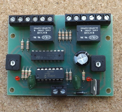
The Dual Timers purpose is to switch on or off an electrical device such as a light bulb, electric motor, track isolation section, servo motor controller, electronic circuit board, signal, etc, for an adjustable amount of time. Alternatively it can be used to switch scenic effects on and off at random intervals. Use of the servo motor controller and the random feature of the Dual Timer allows a scenic feature to be animated at random times, for example a sweeps brush could appear at the top of a chimney at irregular intervals.
The Dual Timer has two timers which can be used separately or linked together (to give sequencing). The second timer can be used to give random timings instead of fixed timings if required. Each timer circuit switches relay contacts whilst timing. These relay contacts are in effect the equivalent of an electrical SPDT (single pole double throw switch) also called a changeover switch. The contacts are completely isolated (separate) from the electrical supply to the board so can switch other circuits without any risk of inadvertant shorts. The time is adjusted with pots. Adjustment is made by rotating them with a small screwdriver. The timing interval can be adjusted between 9 and 132 seconds. An indication of the length of timing is given by the LED fitted to the board. There is a LED for each timing circuit. Whilst timing the LED flashes; the longer the flash length the longer the timing interval.
Description of the Terminals

0V - negative power supply connection.
+ - positive power supply connection.
The Dual Timer needs 12 to 16 volts either AC or DC connecting to 0V and + to provide it with power for its circuitry.
in1 - Connecting this terminal to 0V starts timer 1 timing. This may be via a push button, reed, toggle switch, micro switch or a relay contact. Alternatively many of our boards have a terminal which switches to 0V for example the IRDOT-1 (terminal 2) or IRDOT-P (terminal P) or Servo Motor Controller (terminal F) and any of these could be used to start a timer timing.
The length of timing is the same regardless of whether the 0V is removed during timing or still present after timing has ended. For example if the timer operates a signal and you have a switch to start the timer which is set for 20 seconds, operating the switch for 3 seconds will cause the signal to change for 20 seconds. But if you throw the switch for 40 seconds the signal will still only change for 20 seconds.
However for timing to start for a second time the first 0V pulse must have ended and a second 0V must be applied to “in1”. For example suppose; terminal 2 of an IRDOT-1 is connected to “in1”. Timer1 is connected to an electric motor and adjusted to switch the motor on for 30 seconds. When a train stops over the IRDOT-1 the electric motor will switch on for 30 seconds irrespective of whether the train remains over the IRDOT-1 for 15 seconds or 5 minutes. The motor will not restart until that train has left and a new one arrives causing a new 0V pulse. This pulse is ignored if the timer is still timing. You can connect more than one switch or output terminal to "in1". This allows several different things to trigger the timer.

start
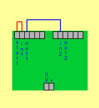
When power is connected to the board start gives an 0V pulse which lasts for 5 seconds. This terminal is used when you require one or both of the timers to automatically start timing when you switch the power on. Connect the start terminal to in1, in2 or both. The diagram shows start connected to in1. (red line). Out1 is connected to in2 (blue line). On powering the board start will give an 0V pulse to in1 starting timer1 timing. When timer1 finishes timing out1 will give a 0V pulse to in2starting timer 2 timing.
Out1 When timer1 has finished timing this terminal gives a short 0V pulse. Its purpose is to activate a second timer when timer1 has stopped timing. Out1 can also be used to activate another circuit for example to latch a latching relay board.
com, B and A These connect to timer1s relay contacts. A relay is in effect a switch operated by electricity rather than being manually changed.

com - common relay contact
A - relay contact connects to “com” when not timing (normally closed)
B - this relay contact connects to com when timing (normally open)
The diagram shows the position of the relay contacts with timer 1 not timing and timer 2 timing. The relay contacts act as a SPDT (changeover) switch. The relay contacts allow the timer to either switch something on whilst timing (use com and B or switch something off whilst timing (use com and A). The com and A arrangement is used for the automated storage sidings where the normally closed contact isolates the storage sidings when the timer is triggered by a train arriving at the IRDOT-P. This gives the time delay between a train entering and the next one leaving the storage sidings. Note the relay contacts have no electrical connection to the rest of the Dual Timer board. This allows them to be used to switch different electrical circuits, for example track isolation sections. Treat them exactly as you would SPDT (changeover) switches. The relay contacts are rated at 3 amps.
RAND - This terminal is for random operation. For example it can activate a dual servo motor controller to make a crane, forklift truck or figure etc move at random. It could also be used to switch a light on and off at random.

Whilst the RAND terminal is connected to 0V (shown by the black line) timer 2s relay is switched off and on in a random sequence. After every random timing the relay switches from on to off or off to on. At the end of each random interval out2 will switch to 0V to give a short pulse. If it is required to activate a relay for a fixed time at random intervals out2 may be connected to in1 (shown by the blue line). This will cause the relay contacts of timer 1 to give a fixed length pulse at the end of every random interval. This is shown in the diagram. The average length of random timings can be adjusted with pot2. If connecting to a servo motor controller a wire from the 0V terminal should be connected to com and B should be connected to S on the servo motor controller. Both circuit boards should be powered from the same power supply.
in2 - Starts timer 2 when 0V applied. Functions identically to in1.
out2 - Functions identically to “out1.
com - Timer 2 common relay contact.
B - Timer2 relay contact, connects to com when timer is timing.
A - Timer2 relay contact, connects to com when not timing.
Chaining timers together to make a sequencer

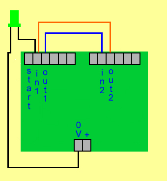
The two timers of the Dual Timer are shown connected together. By connecting out1 to in2 (blue line) and out2 to in1 (orange line) the two timers will time alternatively indefinitely. As they both have an independent timing setting you can adjust them so that for example timer 1 closes its contacts for 14 seconds every 30 seconds. This idea can be extended to include other Dual Timers in the sequence by connecting "out2" to the "in1" of further boards.
However one of the timers needs to receive an initial pulse to start this sequence when the power is first turned on. The initial pulse could be provided by either the start terminal, a push button switch, an IRDOT-1 etc. A push button (push to make) switch is shown on the diagram. This is wired to connect 0V to in1 when pushed and so starts the sequence. If you wish to stop the sequence then one of the connections to either "in1" or "in2" must be broken by either a switch or relay contact.
SPECIFICATION Voltage 12 to 16 volts, AC or DC
SIZE Length x Width 2.9 x 2.2 Inches 74 x 62 Millimetres