Tel. 01538 756800
IRDOT-3D

Uses
Train detection and isolation. Moving up a row of trains automatically after the first departs. This is compatible with dc and dcc model railways.
Gradual braking and acceleration for DCC layouts, (Brake on DC for DCC chipped engines)
Preventing collisions by isolating a line approaching a diamond crossing.
Switching on a level crossing light flasher whilst a train passes.
Operating 2 Aspect (red green) signals. The IRDOT-3D will operate bulb or LED signals.
Switching polarity on a dcc reverse loop.
Operating Servo Controllers and the Bouncing Semaphore Controller to change semaphore signals on a trains approach and to animate lineside effects with the movement of trains.
Terminal arrangement


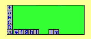
The diagram on the left shows the terminal arrangement of the IRDOT-3D board. Terminals + and V0 are for powering the board. Terminals A, B, C, D, e and f are for accessing the internal dpdt (double pole double throw contacts), the operation of these contacts is shown in the right hand diagram. These contacts are completely isolated from the IRDOT-3Ds power. In other words the contacts have no electrical connection to the rest of the IRDOT-3D electronics. This simplifies wiring as it prevents unintended short circuits through the IRDOT-3Ds power supply. The contacts are rated for currents up to 5Amps.
Terminals g, h and i are for adjusting the timing delay. The IRDOT-3D detects a train as soon as the leading part of the train reaches the IRDOT-3Ds infra red detector, after the train passes over the infra red the timer starts timing, whilst it is timing the contacts remain in their detected position. This makes the IRDOT-3D very useful for a range of purposes.
Terminals l and m are for wiring to LEDs. They allow LEDs for detection and non detection or bicolour LEDs which chang colour as the train is detected. The timing delay is also applied to the LEDs.
All connections to the IRDOT-3D are made via screw terminals.
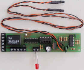
The IRDOT-3Ds built in timer overcomes the following potential problem. A train passing over an infra red detector will give individual detections for each wagon or coach. (during the gap between wagons there is nothing for the infra red beam to reflect off). If your aim is to detect a whole train this is unsatisfactory. When the IRDOT-3D senses a gap its timer starts timing. If the next wagon is detected the timer resets. The timer therefore causes the IRDOT-3D to give a single detection for the whole train. The IRDOT-3D is normally fitted beneath the baseboard with the infra red detector and emitter located in a hole between the sleepers.
Moving up a row of trains automatically after the first departs

This is useful for hidden sidings and fiddle yards and works with either DC or DCC. The diagram shows the wiring of IRDOT-3D units to automatically move a queue of trains up into empty sections left when the front train departs. The departure of the front train (blue section) is controlled by the operator pushing a push button switch. The IRDOT-3Ds also provide LED indication of the occupied sections. The diagram shows three sections blue, green and yellow, separated by isolation breaks. Each section can hold a train. In each section there is an IRDOT-3D positioned at +. The IRDOT-3D is positioned so that the whole train is completely on the section when it is detected. Track power connections to the sections are through the IRDOT-3Ds double pole contacts. When no train is over the IRDOT-3D the contacts A and C or B and e connect together powering the sections of the track. Further sections may be added to the left.
A train moves into the yellow section powered through the IRDOT-3D in the yellow section. The train is detected by the yellow IRDOT-3D which cuts off its power to the track. If there is a train in the green section the train will stop. If there is no train in the green section the track in the yellow section will still be powered via the green sections IRDOT-3D. As it is still powered the train will pass through the yellow section into the green section.
The same operation applies to a train travelling from the green to blue sections. As many sections as required can be wired. The train will stop in the blue section when it reaches the blue sections IRDOT-3D and wait until the push button switch is pressed. The push button switch is used to connect power to the track. The switch should be a "push to make" type.
The wiring could be changed slightly to allow the operation to be completely automatic without the need for the push button switch. The train arriving on the yellow section would cause the train on the blue section to depart. The unused yellow contacts B and D are used in place of the push button switch. B and D are joined connecting power to the track when a train reaches the yellow section.
Gradual braking and acceleration for DCC layouts, (Brake on DC)
Brake on DC is a feature of DCC chips. It instructs the engine to gradually brake to a stop. Interesting applications include DCC station stops, signal stops, approaches to termini, approaches to junctions, speed restrictions and even automatically slowing banking engines. As well as the gradual braking being more realistic another advantage is that lights and sounds continue working when the engine has stopped. When DCC power is switched back the train will accelerate at a rate dependent on the chips acceleration CV setting.
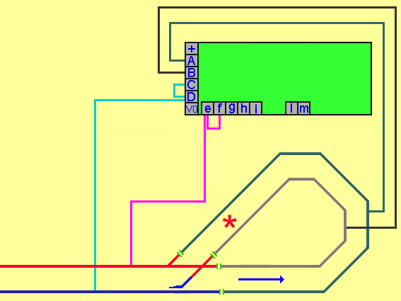
The IRDOT-3D gives a straightforward way of using the DCC brake on DC function. When an engine fitted with a DCC chip runs from DCC to fixed 12 Volt DC powered track the engine slows down gradually to a stop. A problem with brake on DCC is that as the engine crosses from the DCC track to the DC track its wheels will bridge the two. This usually short circuits the DCC power.

Using the IRDOT-3D prevents this happening. The diagram shows a section of track with one rail (in light blue) isolated from the DCC track. The isolated track is switched from DCC to 12 Volts DC when the IRDOT-3D detects a train. The IRDOT-3D is positioned on the isolated section so that an engine detected from this position will have all its wheels on the isolated section avoiding a short circuit. Until a train is detected the IRDOT-3D connects DCC to the isolated section. (because A and C are connected by the IRDOT-3Ds contacts when it is not detecting. When the IRDOT-3D detects the engine at the front of the train it switches 12 Volts DC to the isolated track as A and f are now connected by the IRDOT3Ds internal contacts. The 12 Volts DC remains connected to the track whilst the IRDOT-3D is timing. The engine gradually slows down and stops in response to the 12 Volts DC. When the timing ends the IRDOT-3D switches DCC to the isolated track. The engine now gradually accelerates. For the train to restart after the timing interval the train must stop clear of the IRDOT-3D. If the train stopped over the IRDOT-3D the IRDOT-3D would still be detecting so 12 Volts DC would continue to be connected to the track. If this is a problem you could use a modified version of the Simple Station Stop. The Simple Station Stop times for a fixed time regardless of whether or not the train remains detected. The rate of braking is set by CV 4 and the rate of acceleration by CV 3. Brake on DC works best if the chip is set to DCC only mode (in CV 29). A 12 volt regulated power supply is shown supplying the power to be switched to the track.
With DC operation, when you look in the direction the train is travelling, the right hand rail is positive. Brake on DC requires the opposite the left hand rail needs to be positive.
Only one rail is switched in this diagram. As the two sources of power are seperate connecting them together on the lower rail is permissable. However there is no reason why both rails should not be switched. This may be worth doing if the same 12 volts supply is used for several sections with trains travelling in both directions as it will avoid possible short circuits. If only one rail is switched it leaves spare contacts on the IRDOT-3D which could operate a 2 aspect signal. The signal would show red whilst the train was slowing and waiting in the brake on dc section.
Operating 2 aspect signals with the IRDOT-3D
The IRDOT-3D can operate a 2 aspect signal, either bulb or LED. To make the signal operate like a semaphore signal (where the signal is normally at red until the train approaches, then changes to green until the train passes) fit the IRDOT-3D in front of the signal where you want the signal to change to green. The signal remains at green whilst the IRDOT-3D is timing.
Alternatively the signal can normally be at green and change to red for a set time after the train has passed the signal. For this the IRDOT-3D is positioned after the signal where you want the signal to change to red. The signal remains at red whilst the IRDOT-3D is timing. The diagram shows the wiring to the signals. The signals may share the IRDOT-3Ds power supply or they can use a separate supply. Terminals A, C and f work in exactly the same way as a changeover switch. (SPDT). The common wire (black) from the signal goes straight to the power supply. Red and green go to the C and f terminals. Terminal A (the common of the switch) is wired to the power supply to complete the circuit. Resistors supplied by the signal manufacturer must be used.
If you are already using both the contacts to operate something other than the signal (isolation sections for example) you can operate a 2 aspect common negative LED signal from the terminals intended for the train detection LEDS. Wire the red and green wires to terminal l and m and the common wire to terminal 0V. No resistors are required in this case as they are built into the board. A semaphore signal can also be operated automatically. Possible ways to make the signal move are: Servo motor- use the IRDOT-3D to switch a servo motor controller board.
Slow motion point motor- use the IRDOT-3D to reverse polarity to the point motor. Memory wire also known as muscle wire- use an IRDOT-3D contact to switch on and off the current through the memory wire. For more advanced signal operation see our IRDASC signal controllers.
To isolate a crossing line to prevent collisions.
To prevent collisions when a train crosses a mainline an IRDOT-3D located on the mainline can be used to isolate a section on the crossing line. One contact can be used to isolate one rail and the other contact to operate a signal, changing the signal to red when the track is isolated. This only works with trains travelling in one direction on the mainline. Our Diamond Crossing Detector will work with trains travelling in both directions. To switch level crossing lights whilst a train passes. Position the IRDOT-3D on the approach to the level crossing. One of the contacts can be wired to switch on flashing lights and the other contact can be wired to operate a device for raising or lowering the barriers. This only works for the train travelling in one direction. For operation with trains travelling in both directions on either single or double track see our Level Crossing Controller.
DCC reverse loops
 The IRDOT-3D is useful for allowing trains to run non
stop around a DCC powered reverse loop. The IRDOT-3D will change the
polarity of the rails whilst it is detecting the
train and timing.
As DCC engines travel forwards or backwards regardless of the polarity of the track they will continue in the same direction after the polarity has reversed. However reversing the polarity prevents a short circuit when the train reaches the point. The point can be made to automatically change. It could be fitted with a spring to hold it over for approaching trains, departing trains would push the point blades across against the tension of the spring. Alternatively IRDOT-P units could be used to switch the point across. This reverse loop requires all trains to run around it anti clockwise. For
clarity the power supply connections are not shown in the diagrams. More information about reverse loops is in the reverse loop section.
Delay Times
As supplied the IRDOT-3D has a 3 second delay, i.e. it detects a train immediately but continues timing for 3 seconds after the train has left. By connecting wires from the g, h, and i terminals to the 0V terminal longer delays are obtained.
| Table showing adjustments to the delay times |
Delay | terminal g | terminal h | terminal i |
|---|---|---|---|
| 3 seconds | no connection | no connection | no connection |
| 6seconds | no connection | no connection | 0V |
| 9seconds | no connection | 0V | no connection |
| 12 seconds | no connection | 0V | 0V |
| 15 seconds | 0V | no connection | no connection |
| 18 seconds | 0V | no connection | 0V |
| 21 seconds | 0V | 0V | no connection |
| 24 seconds | 0V | 0V | 0V |

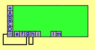
This diagram shows how an IRDOT-3D is connected to give a delay. Referring to the table no connection has been made to terminal i and both g and h are wired to terminal 0V so the length of the timing after the train has departed will be 21 seconds.
LED wiring
The IRDOT-3D is supplied with a red 5mm diameter LED screwed into the terminals l and k, long leg to l short leg to k. This LED will light when a train is detected and continue lit until the timing has finished. A second LED may be fitted to the same terminals long leg to k short leg to l. This LED will light when not detecting or timing. If a number of IRDOT-3Ds are used each with a single LED these LEDs can be wired long leg to l short leg to "0V".The advantage to this is that "0V" is a common connection thus nearly halving the number of wires needed.

Fitting to the baseboard
The unit is screwed to the underside of the baseboard with the infra red emitter and detector located in a hole between the sleepers. It is easiest to install the units after laying the track. Drill a small pilot hole between the sleepers. Fit an 8mm drill bit marked with tape for slightly less than the base board thickness. Drill from underneath the baseboard following the pilot hole. Cut or file the small amount of baseboard material left between the sleepers. Install the unit, and then fill the remainder of the hole with modelling material. Blue tack will hold the units in place temporarily. When fitted to Z or N gauge track the gap between sleepers will be less than the diameter of the infra red detector and emitter. However, the modules work well provided the emitter and detector are fitted touching the underside of two adjacent sleepers. This positioning prevents reflections off the sleepers causing detection. The IRDOT-3D will also operate on its side placed alongside the track. If you wish to do this be careful that you do not detect trains on parallel tracks. The infra red devices can be angled slightly upwards to avoid detecting trains on parallel tracks.
Extended sensors

The standard IRDOT-3D boards are supplied with the infra red detector and emitter soldered to the non component side of the board. They are 22mm long so will be suitable for baseboards up to this depth. For situations where the baseboards are thicker than this or where supporting timbers are in the way we can supply the IRDOT-3D with the emitter and detector attached to 18 inch wire leads.
Broken beam operation
If the extended wire version (IRDOT-3DEW) of the IRDOT-3D is used the leads can be placed pointing towards one another. Instead of detecting trains by reflecting the infra red the IRDOT-3D now detects trains breaking the beam. The IRDOT-3D will work with the emitter and detector up to 2 feet apart. If the beam is angled across the track then gaps between wagons are ignored. Using the IRDOT-3D with the broken beam reverses its operation ie the former undetected LED now lights when you detect a train and the operation of all the contacts is reversed. The time delay will wrongly cause a delay between the beam being broken and LEDs and contacts changing. We can supply the IRDOT-3D specifically for broken beam detection with the timer corrected.
Voltage 12 to 16 volts AC or DC
Dimensions:
Length x width 123mm x 31mm (4.8 x 1.2 inches)
Height of infra red 22mm (0.9 inches)