Tel.
01538 756800
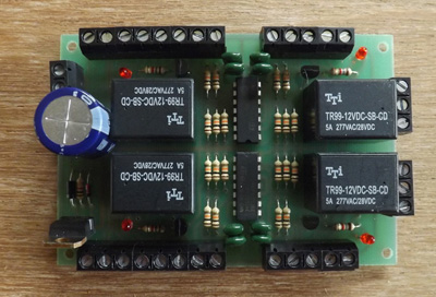
Latching Relay Board

The latching relay board is available in 4 relay and 2 relay versions. Each relay has double pole double throw contacts. This is shown in different colours in the diagram. Built into the board is a power supply which allows the board to be powered by any voltage from 12 to 16 volts of either AC or DC. Power supply connections are made to terminals "+" and "0V". All the relay contacts are accessible for wiring from screw terminals. Four LEDs are fitted to the board. Each LED lights when its associated relay is energised. The relays are rated for switching a current of up to 5 amps
The latching relay board has the same arrangement of relay contacts as the relay board. The difference is that the latching relay board has extra electronics to latch the relays. The first relay has poles "1" and "2", the second "3" and "4", the third "5"and "6" and the fourth "7" and "8". If the top right "S" is connected to 0 volts the relay contacts will connect "C3" to "B3"; and "C4" to "B4".
Connecting 0 volts to the "set" ("S") terminal switches on the relay. The relay remains switched on after the 0 volts is disconnected. When 0 volts is connected to the "reset" ("R") terminal the relay switches off and stays off after the 0 volts is disconnected. It is the initial pulse of 0 volts onto "S" or "R" which switches the relay on or off. IRDOTs, IRDASCs, IRDOT-Ps, push button switches, dual delay timers, and relay contacts can all be wired to operate the "set" and "reset" terminals.

The applications for this unit are numerous. As each relay is double pole its contacts can be wired to reverse the track power. This allows use for passing loops and shuttles. It can also be used for signalling, automatic level crossings, switching power to tracks, slow motion point motors etc.
Further flexibility is possible by connecting several devices to operate the same "set" or "reset" terminal. By connecting "S" terminals and "R" terminals a 4, 6 or 8 pole relay can be formed.
The terminals are arranged so that "C" is common "A" is normally closed and "B" is normally open. The number after the letter refers to the pole of the relay. The first relay has poles "1" and "2", the second "3" and "4", the third "5" and "6" and the fourth "7" and "8". If the top right "S" is connected to 0 volts the relay contacts will connect "C3" to "B3"; and "C4" to "B4". Connecting 0 volts to "S" will connect "C3" to "A3" and "C4" to "A4".
Operating with a switch or relay contact

Any type of switch may be used ie reed switch, toggle switch relay contacts etc.
Operating with an IRDOT-1 etc

The diagram shows how two IRDOT 1s may be connected to switch the relay connected to terminals C3 A3 B3 C4 A4 B4. As the train is detected by one IRDOT the relay switches on when connected by the second the relay switches off. Other units such as the IRDOT-P ("P" terminal) can be used in the same way. Note both the IRDOTs and relay board must use the same power supply and have "0V" connected to "6".
Reverse Loops

Wiring for reversal of track polarity. Controller is connected to both "C" terminals, A terminal of one relay pole is connected to "B" terminal of other relay pole. When R or S is activated the track polarity will change. Often it is convenient to use the P terminal of IRDOT-P units as they will then cause the polarity ro change as the points are automatically changed.
Dimensions
width
length