Tel. 01538 756800
Motorised private siding gate kit


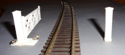
Factories, mines, gasworks, quarries etc often had their own sidings or even rail networks. Where these connected to the railway company they were required to have a gate across the line. This kit replicates this with a motorised 00 gauge gate. The gate can be operated with an on/off switch (included) or it can be connected to our DCC Accessory Decoder 1. Or if you have servo controlled points it can be operated by the F terminal of the Single or Dual Servo Motor Controller operating the point into the private siding. This has the advantage that the gate moves only after the point has moved to the siding.
Kit contents


Digital Servo Motor
Servo Motor Bracket
piano wire
Single ServoMotorController
Toggle switchon/off
three-panel-gate
All mounting screws,nuts and bolts.
Not included are power, 12 volts DC is preferable and wire for the switch.
Installation
The gate bearing and pivot are all made as a single 3D printed unit so that assembly and installation is very easy. The bearing locates in a 10mm diameter hole drilled in the baseboard. It is designed to be a very loose fit in the hole. This overcomes the difficulty of drilling holes square in the baseboard. The base at the gates post has 2 screw holes to fix it to the baseboard with small woodscrews. It is this base which ensures the post is square so making the gate level. A crank (which is snipped off the crossing assembly) is a push fit on the bottom of the pivot. This prevents the gate from wobbling. The servo motor crank then just needs connecting to this crank with a piece of piano wire. The servo motor bracket is bent along its etched line and the servo motor is bolted to the bracket. The bracket is then screwed in position. The crank arm is fitted to the servo motor. The 2 cranks will be joined by a length of piano wire. The Single Servo Motor Control board is wired to its switch and connected to 12 Volts DC. The speed button is held down on the Single Servo Motor Controller for 5 seconds. This causes the Servo motor to move to the midpoint of its travel. The servo motors crank can then be fitted pointing straight down. The gate is now held at the half way position between open and shut and the 2 cranks are connected with piano wire.
This kit is for manual operation ie the gates are opened and closed by throwing the switch. You could use the DCC Accessory Decoder 1 or a contact on the points approaching the siding operate the gate if youpreferred.