Tel.
01538 756800
POINT INDICATORS

When solenoid point motors such as Hornby Peco or Seep are used they need to be operated by a momemantary pulse of current. These point motots are not designed for a continuous current in fact poweting these point motors contimuosly rather than with a short burst a which may cause them to overheat and be damage them. Momrntary toggle switches push bitton switches or strd and probe are all used to create the momentary pulse of current the only disadvantage is that these do methods not show which way the point is set.
The purpose of the POINT INDICATOR boards is to light LEDs to show which way the point is set. The point indicator board senses the current when the switch is thrown and remembers this (even when the power is removed from the model railway). It is very suited for use in conjunction with a schematic diagram.
There are several versions of the point indicator. Each of these monitors four standard points.
The point indicator Standard lights control panel mounted LEDs to show the settings of points operated by solenoid point motors. It has the resistors to limit the current built into the board and is the simplest point indicator to use.
The point indicator_SO has a more powerfull output capable of switching a large number of LEDs, a relay or a mixture of both. Although it is more versatile in use ur requires external resistots to be wired into the lead to each LED.
The point indicator relay works as the point indicator standard but has four sets of isilated spdt contacts (equivalent to changeover switches operated by the points position. These are usefull for switching electricity to the frogs of points especially with N gaige points where the contact of the point blades often seems to be unreliable in conducting electricuty to the frogs.The contacts are also usefull for signalling.
All the Point Indicators shows the direction of 4 points. The setting of each point is shown with 2 LEDs (intended for wiring back to a control panel). The Point Indicator has a memory which remembers the point settings whilst power is turned off. The diagram shows the usual/existing wiring to operate the points as brown and grey lines and the extra wiring for the point indicator as blue, red and green lines.
All these boards can be supplied fot either analogue or digital (dcc) control of the point motors.
The Point Indicator will work with points powered from either a CDU (capacitor discharge unit) or an AC transformer. Points powered by a CDU must be wired so that the common connection to the point motors is from the negative side of the CDU (see later for common positive version). The positive connection from the CDU is connected to the point motor via the switches. See the diagram above. The reason for this is that the Point Indicator board senses positive pulses from the switch to the point motor. The Point Indicator can be powered from 12 volts to 24 volts to allow it to work from the supply used for the CDU. The top 2 point motors in the diagrams are shown wired as "Peco" point motors, these have 4 connections. The bottom 2 are "Seep" which have a common connection in the centre of the point motor.

 The
Point Indicator can be supplied with red, green or yellow 3mm dia.. LEDs.
For example green is lit when a point is set to the main route, red when
set to a subsidiary route. Alternatively all yellow LEDs can be used to
represent a diagram inside a signal box. The Point
Indicator uses the fact that LEDs only light when the current
passes in one direction. This allows two wires to operate 2 LEDs as the
point indicator reverses the voltage at the terminal block. Current either
flows from L1A to L1B or from L1B to L1A.
The
Point Indicator can be supplied with red, green or yellow 3mm dia.. LEDs.
For example green is lit when a point is set to the main route, red when
set to a subsidiary route. Alternatively all yellow LEDs can be used to
represent a diagram inside a signal box. The Point
Indicator uses the fact that LEDs only light when the current
passes in one direction. This allows two wires to operate 2 LEDs as the
point indicator reverses the voltage at the terminal block. Current either
flows from L1A to L1B or from L1B to L1A.
It is possible to connect an extra pair of LEDs to the point indicator. The diagram below shows how the LEDs are wired. Note one leg of the LED is a little longer than the other; this is to show the polarity of the LED. (LEDs only light if the current flows in the correct direction) Wiring for an LED to light the track selected If the point is set to "A" then the long leg of A will be positive, hence A will light but "B" and "C" cannot lightas their short legs are positive. If the point is set to either B or C, A will not light (the long leg is negative), but either B or C can light depending upon the setting of the second point.
POINT INDICATOR-SO (Switching Output)

This
version of the Point Indicator has a more powerful output to switch
numbers of LEDs, relays or operate inputs of the IRDASC units. The Point Indicator-SO has an output stage composed of open collector npn
transistors. This gives many options when using the Point Indicator-SO.
If you are unfamiliar with transistors the output stage is equivalent to
the diagram on the right and can be thought of as consisting of 4
changeover switches with the common terminal of each switch connected to
the negative terminal. This means that when the point switches one way,
terminal "L2A" will be connected to "-" and "L2B"will
be an open circuit. When the point switches the other way, "L2A" will
be open circuit and "L2B" connected to "-". open
circuit means no electrical connection is present on the terminal)
LEDs
The
Point Indicator-SO allows a number of LEDs to be switched at the same
time. This may be required for layouts with several operating positions.
Th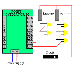 e
diagram shows how to connect a number of LEDs. If the point indicator
board is powered from AC then it is necessary to use a diode to protect
the LEDs from being damaged from reverse voltages. LEDs only light when
current flows through them in one direction. This direction is generally
indicated by the LED having a long and a short leg. A resistor value of
1K8 (1800ohms) should be suitable unless a large number of LEDs are used
in which case a lower resistor value may be necessary to keep the LEDs
bright. Note how the short leg of each LED is chained to the long
leg of the neighbouring LED. Also note that the diode must be correctly
orientated. (A diode is a one way valve for electricity) . This is
shown by the band on the diode.
e
diagram shows how to connect a number of LEDs. If the point indicator
board is powered from AC then it is necessary to use a diode to protect
the LEDs from being damaged from reverse voltages. LEDs only light when
current flows through them in one direction. This direction is generally
indicated by the LED having a long and a short leg. A resistor value of
1K8 (1800ohms) should be suitable unless a large number of LEDs are used
in which case a lower resistor value may be necessary to keep the LEDs
bright. Note how the short leg of each LED is chained to the long
leg of the neighbouring LED. Also note that the diode must be correctly
orientated. (A diode is a one way valve for electricity) . This is
shown by the band on the diode.
Relays
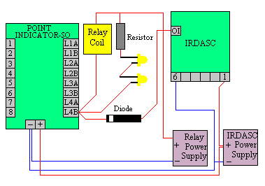
The output stage can switch relays. Two relay coils are shown connected to terminals L2B and L3B. As commonly used relays require smoothed DC (usually 12volts) to operate, a separate power supply may be required for the relays. The wiring for this is shown in the diagram
Signalling
The
outputs may also be used to operate "OI" inputs of the IRDASC
signal control units. If relays and LEDs are being used it will be
necessary to use a diode. The outputs can also be used to operate 4 bulb
or LED signals, one on each track approaching the point.
Bicolour LEDs

The two red LEDs are common cathode and the green LED is common anode.
Common Positive Versions
Some DCC accessory decoders and some manufacturers' ready built switch/CDU units use common positive point wiring i.e. the CDU positive goes to the common of the point motors. We can also supply versions of the Point Indicator and Point Indicator- SO for this type of wiring. Unfortunately with the common positive version if more than one board is used each one requires a seperate power supply to avoid short circuits due to the accessory decoders wiring.
Voltage 12 to 16 volts, AC or DC
SIZE Length x Width 3.1 x 1.979 Inches 79 x 49 Millimetres

The Point Indicator Relay detects the position of 4
solenoid point motors. When a solenoid point motor is switched the point
indicator lights an LED and switches a relay. The setting of each point is shown with 2 LEDs (intended for wiring
back to a control panel). The Point Indicator has a memory which remembers
the point settings whilst power is turned off. The diagram shows the usual wiring to operate the points and the extra wiring for the point indicator as green lines
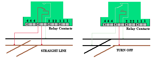
Wiring To Relay Contacts

Along the bottom of the diagram are 12 terminals grouped in 3s. These allow connection to the relay contacts. When, for example, the switch connected to the input 1 terminals is operated the LEDs connected to the terminal 1s on the right will change and the relay contacts connected to terminals 1 on the lower row will also change. The relay contacts are SPDT i.e. identical to a changeover switch. "C" marks the common connection. No power is on these contacts. The diagram above shows the internal contacts present in each of the 4 relays and how to connect these to switch the frog of a point. This overcomes problems with poor contact between the point blades and stock rails. These seem to be more troublesome with small gauges. The relays are also useful for switching signals. The diagrams on the right show how the POINT INDICATOR- RELAY switches electricity to the appropriate rails. This overcomes problems with poor point blade contacts. These diagrams show electrofrog points. The Point Indicator works equally well for insulfrog points.
Voltage 12 to 16 volts AC or DC.
Length x Width 80 x78 mm