Tel. 01538 756800
British Railway Signalling
The following description is for British Railway Signalling. American and European signalling follow similar principles but with differences in some of the signal displays.
Railway signalling is the result of years of effort to make the railways safe whilst allowing an ever increasingly fast and more frequent train service to run. There are two main types of signals semaphore and colour light. Semaphore signals consist of a moving arm generally activated mechanically by a linkage from a nearby signal box. Colour light signals consist of 2, 3 or 4 lights on a post and are usually controlled by a single signal box controlling a large area of lines. On little used lines semaphore signals survive to this day.
Semaphore signals

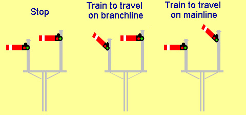
Both upper and lower quadrant stop signals show danger (ie tell the driver to stop) when they are in the horizontal position but display clear differently as shown in the diagram. Stop signals have red arms with a white band when viewed from the front and white arms with a black band when viewed from the back. Semaphore signals needed to be seen at night and in poor visibility so have an oil lamp fixed to the signal post. It seems old fashioned not to use electricity and to subject an employee to climb the ladder at night in a howling gale to refill the lamp but the arm of the signal comes down with such a thump that if an electric light was used the vibrations would soon break the filament. Attached to the signal arm is a pair of filters arranged so that from the front a red light is seen when the signal is at danger and a green light when the signal is at clear.
Apart from signals being necessary at junctions and stations the line was generally split into blocks, each block being under the control of a signalman. To prevent collisions only one moving train was allowed on a line in a block. Hence there may be signals with a signal box to control them in the middle of nowhere. Signal boxes may also be found at level crossings where one of the signal man's duties is to open and shut the crossing gates and keep signals at danger until he is sure crossings are clear. Signal men communicated telegraphically and electrically with block instruments between each other. This explains the presence of telegraph poles alongside railways in the past. Wiring associated with railways now runs in concrete troughs.

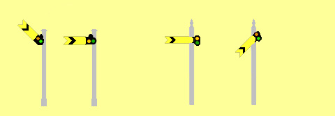
Trains take a long distance to stop. By the time a driver of a fast train sees a signal it is usually too late to stop without running past the signal and so possibly crashing into any train in the next block. To give the driver warning of the position of the signal ahead, distant signals are located around a quarter of a mile before the stopping signal. When distant signals are in the horizontal position this does not mean the train is to stop, it is a warning for the driver to start braking as the next stopping signal may be at stop. In some circumstances were the train is always going to have to travel slowly fixed distant signals are used. These have an arm which is permeantly fixed in the horizontal position. Distant signals are distinguished from home (stop) signals by colour (yellow with a black chevron on the front and white with a black chevron on the back) and by the notch cut in the end of their arm. Signals viewed from the back are ignored by the train driver.
To prevent signals being set to clear when points along the trains route are adversely set interlocking is used. In a mechanical signal box points were usually moved mechanically by a rod running from the lever in the signal box. On main lines the points would be interlocked to the signals. This was a mechanical arrangement of tappets and rods arranged so that the signal could only be moved to clear when the points were set to its route.
Originally signals were left at the clear position. However accidents resulted when the signal arms iced up in the clear position as this prevented the signal man stopping a train from running into the back of another. So it was realised it was much safer to leave all signals at danger unless a train is approaching when the signal will be set to clear provided the route ahead is correctly set and clear of obstructions. Hence the signal man will return signals to danger immediately the train passes the signal. Although this method of operation was for semaphore signaling some or all of the semaphore signals along a line could be replaced with 2 aspect colour light signals. Red and green signals being used for home and yellow and green for distant. Sometimes the distant signals were colour lights and the stop signals semaphore, the reason being that the distant signal may be 1000 yards from the signal box and it was a great effort to pull the signal on and off due to the friction of all the rodding.
Usually signals are on the left hand side of the track signaled.
Single track lines
These still require signals at the terminus station and at passing loops however there was the possibility of head on collisions on single track lines and so extra safety measures were necessary. One method was to use a token for each section of line The section of line would be between passing loops. A train had to be in possession of this token before being allowed onto the tokens section of line. Where trains passed the drivers would exchange tokens.
Junctions-diverging lines

At a junction two or more signal arms are used to show which route is set. Usually the arm is lower on the less important route. As well as stop signals two distant arms may be used on the distant signal ahead of these stop signals. This type of signal is known as a splitting distant. Colour light signals can use the same principle of two signal heads on the post to indicate to the driver which route is set.
3 and 4 aspect colour light signalling

Colour light signals have advantages over semaphore signals. There lights are more powerfull particularly as they are focused into a narrow beam and can penetrate fog much better than an oil lamp. They are also more easily seen against obstructed backgrounds. There are no mechanical parts in modern colour light signals so they are more reliable and unlike semaphore signals with the friction of mechanical wires running over pulleys there is no limit on the distance they may be from the signal box. However some early colour light signals, called search light signals,had a single bulb and a mechanically controlled frame of filters to change the colour.
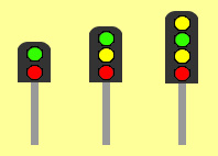
By the number of aspects is meant the number of lights the signal shows. Apart from being called green, yellow (instead of amber) and red the lights are arranged in a different way to road traffic lights. The red light is at the bottom so that it is at the drivers eye level.
The first 4 aspect signals were installed in 1926 on the Southern Railway in conjunction with the electrification of lines. The London and North Eastern Railway installed 4 aspect signals in 1935 to overcome problems with the braking distance when running the "Silver Jubilee" at fast speeds.


 /
/
The diagrams above show how 4 aspect signals change as a train travels along a line. Initially the signals are all at green and when the train passes the first signal it changes to red. As the train travels along it always leaves a red signal behind it. Following trains are warned of this by a yellow and then a double yellow before the red signal. It takes a long distance for trains to stop. The signal displays yellow to warn the driver that the next signal is at red. For very fast lines it is necessary to warn the driver the next signal is at yellow by displaying a double yellow. Signals with the double yellow are called four aspect. Red, yellow and green signals are called three aspect. Because there is no advance warning of a signal being at yellow with 3 aspect signals a longer braking distance is needed so the signals need to be further apart than with 4 aspect signals and so a less trains can occupy the line. Therefore 4 aspect signalling is necessary on busy lines.
Junctions Route Indicators / feathers

In the early days of colour light signals, junctions were signalled with two signal heads on the post copying semaphore signal junctions.
However a different method was adopted. This uses route indicators (also called feathers because of appearance). These consist of a row of 5 white lights which are illuminated when the point is set to the diverging route and the line ahead is clear. If the diverging route is blocked (signal at red) then the feather is not lit. If there are more than one diverging routes then extra feathers are added to the signal. The angle of the feather gives an indication of the direction the diverging route leaves at.
On the approach to a large station there may be many routes the train can take. In these situations a theatre indicator might be used. This is shown on the right of the diagram above. A matrix of lights illuminates to show a number or letter corresponding to the platform number or route the train is to enter.
Ground signals

These are also called shunt signals. They are used for shunting and low speed manoeuvres such as controlling an engine running around its train or trains backing across crossovers or into sidings. Early ground signals had small versions of the semaphore arms used on stop signals. Apart from being on posts near ground level they are sometimes fixed low down on the post of a normal signal. Shunt signals display red for stop and white for clear. The modern light version has two whites for clear and a white and red for stop. The other type of signal shown with a yellow bar or light is often used where a point leads either to the mainline or a headshunt. It may be passed when the yellow line is horizontal or the yellow light is lit provided the points are set to the headshunt but may not be passed if the points are set to the running (main) line.
Conclusions for models
Semaphore signals are at danger unless they need to be at clear. Colour light signals are at clear unless a train has recently passed them.
To have realistic signalling on a model railway some factors to consider are;
The date the model is set in. Very up to date models can use the colour light signals with safety cages. Older models would use safety ring colour light signals. However secondary lines may still be using semaphore signals up to the present day.
Location: The Railway companies before British Rail had different designs of signal. The GWR used lower quadrant signals, the other 3 companies upper quadrant, (before the first world war the majority of signals were lower quadrant). Some of these signals were still in use in the 1960s. Apart from wood for the signal pos,t railway companies used different materials resulting in different appearances of the signals. The Southern Railway had concrete posts, the LNER had steel lattice work and the LMS tubular steel posts. Also some companies signalled more shunting manouvres than others so would have more signals in a station with the same track plan.. Signals last a long time so these differences would still be around in British Rail days
How busy the line is and how fast the trains run on it is another factor to consider.. A busy mainline will have 4 aspect colour light signals, A more subtle difference would be that a busy line with semaphore signals would have the signals closer together so that a stop signal would share its post with the distant signal for the next stop signal along the line. Whereas a less busy line would have the signals spaced further apart so the distant signals would stand on there own.
We have circuit boards to control most types of signals automatically. For 2 aspect signals see IRDASC-1, IRDASC-2, IRDASC-SS, IRDASC-3, Semaphore Sequencer and SA7-SB. For 4 aspect signals see MAS sequencer, MAS Sequencer-RI, IRDASC-4, IRDASC-4RI, IRDASC-5 and IRDASC-5RI. The RI versions control the feather for junctions.