Tel.
01538 756800
SA8 and SA8-S
The SA8 and SA8-S station stops provide a gradual braking as a train approaches the station, and after an adjustable wait in the station a gradual acceleration away from the station.
The SA8 and SA8-S can also be wired so that it remains stopped until a pushbutton switch is pressed. This is very usefull for exhibits as it allows members of the public to start the train. After pressing the push button the signal will change to clear and the train set off after a few seconds delay.
The SA8 and SA8-S can be wired for the following types of operation:
Every train stops at the station.
Alternate trains stop at the station.
Every third train stops at the station.
Trains stop at the station randomly.
The next train wil not stop at the station.
The SA8-S has contacts for controlling a 2 aspect (red and green colour light) starter signal. The signal changes to clear just before the train is to depart and returns to danger after the train has left the station. For non stop trains the signal changes to clear as the train approaches the station and returns to danger after the train has left. The signal control is particularly effective with random operation.
There is a great deal of flexibility in how the SA8 and SA8-S can be used. If you require a more basic station stop look at the Simple Station Stop.
The SA8 can be powered from either AC or DC voltages between 12 and 16 Volts. No controller (throttle) is required. The output to the track is analogue (DC). A controller/throttle is not required. However you may wish use one so that you have a choice of automatic or manual control. This allows, for example, a train to be shunted into siding and replaced by a new train. There are two ways to swop between manual and automatic control. You could use a DPDT (double pole double throw) toggle switch to switch either the SA8 or track output to the track or the controller. Alternatively you can wire a controller into the SA8 board. This is described later. If used on a DCC layout the track used by the SA8 or SA8-S will need to be isolated from the remainder of the layout. Engines with DCC chips will run under the DC (analogue) control provided the DCC chips dual mode CV value is set.

Two train detectors are used. One train detector is in front of the station where the train is to start slowing. The second train detector is positioned where the front of the train is to stop. On reaching the second train detector at the station the train stops. It then waits an adjustable time before accelerating to the maximum speed setting. The train detectors can be either reed switches or IRDOT-1 infra red detectors. Although the SA8 and SA8-S work satisfactorily with reeds these have some disadvantages compared to the IRDOT-1. With reed switch detection each train needs to be fitted with a magnet and so the reed switch needs to be positioned in relation to where the magnet is on the train. For example if a DMU has a magnet fitted at one end then if it runs in the reverse direction it is going to overrun the station.
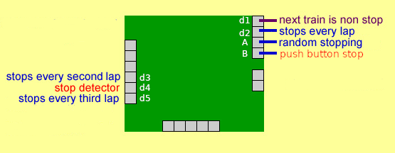
T he operation of the SA8/SA8-S is set by the terminal the start slowing detector is connected to. The diagram shows these terminals labelled in blue. The stop detector always connects to terminal D4. If you wish to change the type of operation frequently a rotary switch could be used to select between the terminals.
The "next train is non stop" terminal can be used to make certain trains run through the station without stopping. It needs to receive a momentary conection to 0V before the train reaches the start slowing detector. One way to use this terminal would be with a reed switch connected to it. Only trains intended to be non stop are fitted with magnets to activate the reed switch, magnets would not be fitted to stopping passenger trains. Another way to use this terminal is when the SA8 or SA8-S is used with automatic storage sidings. The P terminals of certain IRDOT-Ps used in the storage sidings can be connected to this terminal.
 If there is more than one station stop on the same line, a single SA8 can control all the stops. Each stop requires two extra train detectors wiring to the SA8. This will not work with the SA8-S because only one signal is controlled. For a more basic system see the simple station stop.
The diagram on the shows how IRDOT-1 detectors are wired for random stopping.
LED indications
The SA boards have a red and green LED. They indicate the following:
Red LED lit, train is braking or travelling at minimum speed.
Green LED lit train is accelerating or travelling at the maximum speed setting.
Red and green LEDs flashing alternately. This shows the SA8 is timing the halt at the station. The duration of each flash is shorter for a short stop.
Red and green LEDs both constantly lit. This indicates an overload or the track has short circuit.
Speed, acceleration/braking and wait time adjustments
 Adjustments are made by rotating pots with a small screwdriver. These adjust the (wait time) time the train stops at the station. The maximum speed the train travels at. The rate of acceleration or braking and the minimum speed. The minimum speed is set to the slowest speed the train will reliably move at. When the train brakes it slows the train until it is travelling at the minimum speed its purpose is to ensure the train reaches the stop detector.
Tips on setting up the adjustments
Initialy turn the variable resistors with a fine screwdriver to give delay time = short(turn clockwise), min speed = slow (turn clockwise), max speed = fast (turn anti clockwise), ACC/BR (rate of braking/acceleration)=abrupt(turn clockwise).
It may be found easiest to operate the unit so that it stops on each lap whilst making the adjustments. Regardless of its starting position the train will quickly accelerate to maximum speed after switching on power (green LED lit and SA8 signal at red). When the train is detected by the IRDOT-1 at the approach to the station it will rapidly reduce speed and halt (red LED lit on SA8). Adjust the min speed setting until the train just moves. It will then travel to the train detector at the end of the station and stop. The red and green LEDs will now flash alternatively for the delay time. At the end of which the signal will change to green. The red LED will light for a few seconds then on changing to the green LED lit the train will accelerate away. Adjust the maximum speed setting to the required speed (unless using the controller to determine the max speed in which case the maximum speed should be left at max). Each time the train brakes on approaching the station adjust the ACC/BR setting until the train slows to the minimum speed just before reaching the stopping position. The min and max speed adjustments are confusing to set unless acc/brake is set to abrupt because of the effect of electronic inertia. Finally adjust the delay time setting to the desired time. The length of the flashes is proportional to the delay time.
Power supply

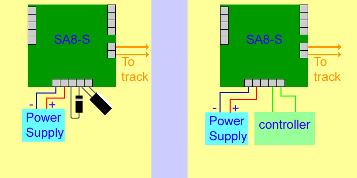
The lefthand diagram shows the SA8 working on its own. The power supply can be either AC or DC. The diode and capacitor supplied attached connect the power supply to the output stage.
The righthand diagram shows how a controller is connected to the output stage. The controller setting detemines the maximum speed and allows the train to be stopped or reversed. When approaching the station the SA8 overrules the controller.
More than one board on an oval

This shows an example of how to connect boards together. The diagram to shows how the SA6 is connected to the SA8 to give a single output to the track. Both units can slow
the train when it has crossed the units start slowing detector. Using the SA6 and SA8 together allows a succesion of different trains to travel through the station automatically with some stopping and others travelling on non stop. The SA8 can also be used on the same oval with the SA5 and SA5-S passing loop boards.
Signal wiring

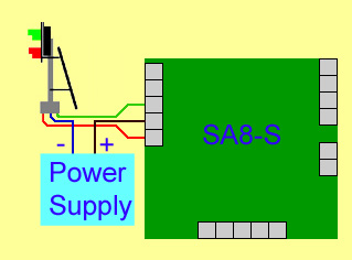
The SA8-S is provided with changeover contacts to operate the starter signal. These contacts have no electrical connection to the power supplied to the SA8-S board and connecting the signal is electrically equivalent to wiring to a SPDT switch. The diagram shows the signal wired to its own power supply however there is no reason why the signal should not share the SA8-S power supply. The instructions contain detailed instructions of connecting different types of signals. The contacts can also be used to work the Servo controller board, memory wire or slow motion point motors for activating semaphore signals.
Overload and scales
Overload protection is built into the SA8. If a current over 1 Amp is drawn from the unit then the overload circuit will prevent the unit from being damaged by switching off power to the track. This fault condition is indicated by the red and green LED's both lighting. As soon as the fault is rectified the unit will resume normal working. The standard unit is fine for N and OO gauges. Due to small size of Z gauge electric motors a small modification is necessary for Z| gauge to ensure that the track voltage does not exceed 9 Volts. O gauge models with modern motors and small LGB models work fine but contact us about modifications to power locomotives with motors that require more than 1 Amp.
SA8 and SA8-S with push button start.
Instead of wiring the stop detector to the D4 terminal on the SA8-S board it is wired to the D7 terminal. A push button (push to make) switch is wired between the 0 and D4 terminals. When the train runs into the station it will wait until the push button switch is pressed. This type of operation is mainly intended for use with model railways that form an exhibit. With this in mind we can supply a modified SA8-S which will make a number of stopping laps (specified by the customer) before the train comes to rest again.There is no point in trains wearing themselves out when nobody is watching.
There is no reason why a detector elsewhere on the layout should not be used in place of the push button switch. This gives the possibility of a train remaing in the station until activated by a second train elsewhere on the layout reaching a certain location.
SA8-DSS for Dapol semaphore signals


Operation is identical to the standard SA8-S. The signal output is modified to work Dapol semaphore signals. The signal must still be powered by 16 Volts AC. The black and red wires connect to this power supply. Instead of connecting to a push button switch the yellow wires connect to the terminal block of the SA8-DSS. Contacts built into the SA8-DSS close briefly connecting these two terminals when the signal is to change.
Train detectors are not included.
Voltage12 to 16 volts, AC or DC
Current consumption Most current is consumed by locomotive so the power supply must match this.
Length 3.7 inches 93 mm
Width 3.7 inches 93 mm