Tel. 01538 756800
Automatic storage sidings
Our units can operate storage sidings on an oval to allow a succesion of different trains to run around an oval automatically. There are two versions either with abrupt halts or with gradual slowing and acceleration of the trains.
The version with abrupt halts is suitable for both dcc and dc (analogue) model railways, the version with gradual slowing is only suitable for dc (analogue) model railways. For both systems there is an adjustable delay between a train arriving and departing. When a train arrives it switches the entry and exit points. The point setting is used to isolate the track the train has arrived on. Electrofrog, insulfrog or any type of point which isolates the track is suitable.
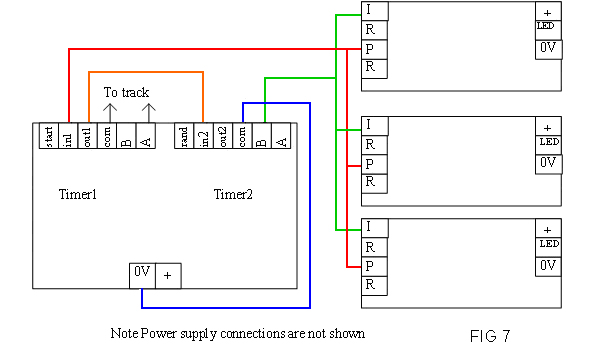
Abrupt stop storage sidings with Dual Timer and one IRDOT-P for every loop.
Any number of sidings/ loops can be automated. At the end of every siding is an IRDOT-P. This does two jobs, it operates two or more solenoid point motors and it sends a message to the Dual Timer that a train has arrived. This message will start the first timer on the Dual Timer. The diagram shows a 3 loop storage siding. When a train arrives at siding 3 for example both the entry and exit points will change when the front of the train reaches the IRDOT-P. This will isolate the train in siding 3 and the new point setting will make the track live on siding 2. However the IRDOT-P will have started the Dual Timer timing. Whilst the Dual Timer is timing

it will open the connection between A and COM so the train on siding 2 will not leave until the timer has finished timing and terminals A and COM are connected together again. The train will now leave siding 2 do a circuit and return to siding 2. On being detected by the IRDOT -P on siding 2 the points will change to siding 1 and the Dual timer will begin timing again.

The connections from the power supply are missed off the diagram to make it clearer to understand. When a train arrives over an IRDOT-P it is detected. The R terminals on the IRDOT-P connect together for 1 second, these are used to give a pulse of power to the point motors. At the same time the P terminal switches to 0 Volts for 1 second. This pulse travels along the red connection to the IN1 terminal of the Dual Timer. When IN1 is connected to 0 Volts the Dual Timer will begin timing (indicated by the timer 1 LED on the Dual Timer flashing) Whilst timer 1 is timing the internal connections from COM and A are open so that the whole sidings have no track power. When timer 1 finishes timing A and COM will reconnect putting track power onto the storage sidings and the line which the points are routed to will become live, and so the train on that line will depart. The second thing that happens when timer 1 finishes timing is that it pulses the OUT1 terminal (this connects to IN2 via the orange wire). Timer 2 will now begin timing.
When the departing train leaves its siding the train will cross over the IRDOT-P on that line. Provided the train stopped in a position where the IRDOT-P still detected the train there will be no problem with this even though there may be losses of detection due to gaps between wagons and carriages. This is because the IRDOT-P needs to recognise several seconds of no detection before it will interpret a new detection as a new train and switch the points (which would derail a departing train). A problem would only arise if the train had stopped in a position where it was not being detected (although it was initially detected there is a possibility that its momentum after the power is turned off could cause this to happen. The second timer eliminates this problem.
SA6 storage sidings
These work in a similar way to the Dual Timer controlled storage sidings. The main difference being the gradual braking and acceleration. An IRDOT-1 is located at the entrance to the storage sidings, this is so that the SA6 knows when a train is approaching the sidings and it will start slowing the train at this point.
SA6-B storage sidings
This works in the same way as the SA6 but has in addition block controls so it can form a block along with the SA7-SB controllers. An alternative use is to use the SA6-B on its own and to connect its block control to an on/off switch so that the train stays in the sidings until the switch is operated.