Tel. 01538 756800
Switches
Switches (and relays) come in different packages for different purposes but all are a means of operating contacts to connect or disconnect electrical circuits. Toggle switches are popular with railway modellers, they are fairly robust, easily fitted, neat and modestly priced. There are many different varieties which fulfill different purposes as will be described. Reed, microswitches and push button switches can also be usefull and are also described.
On/Off switch SPST


The simplest type of switch is an on off switch. This will have 2 connectors. In one position of the switch these 2 connectors are joined together by the contacts inside the switch. In the other position of the switch these two contacts are not connected. Uses of these switches are track isolation sections, switching lights on and off in model buildings.
Change over switch SPDT switches

If you had a 2 aspect home colour light signal to wire up you could use an on off switch to turn the red LED on and off and a second on off switch to turn the green LED on and off, although this would work its an overcomplicated and unsatisfactory way to wire the signal. Without care when operating the switch you could have either both red and green lit at the same time or neither lit.
A better solution is a single switch which would light the red LED in one position of the switch and the green LED in the other position of the switch. This type of switch is called a changeover or SPDT (single pole double throw). It has three solder tags the central one is usually referred to as the common as it is the tag which connects ro one or other of the 2 outer tags.
By disregarding the extra contact it can still be used as an on off switch.
Uses of centre off change over SPDT switches

You may want to use SPDT switch to operate 2 electric motors to control a crane for example. As well as being able to switch either of the electric motors on you would need to be able to switch them both off. Centre off SPDT switches provide this. They have a central position for the lever. When the lever is in this position all three solder tags are disconnected from one another. The diagram above has red letters for the contacts that are connected with the lever in particular positions.
Single pole double throw momentary switch
Momentary switches are switches which are spring loaded to return the switch to the centre position. Solenoid point motors such as SEEP Peco and Hornby need a short burst of power. They can be damaged by continuous power. They also have 2 solenoids built into the point motor, one to move the point motor left the other to move it right. Momentary SPDT switches are very suited to operating this type of point motor. As soon as they are released they return to the centre position so the point motors cannot be left accidently powered.
Double pole double throw DPDT switch
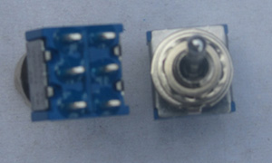
A Double Pole Double Throw switch is two SPDT switches side by side in the same case but both worked by the same toggle lever. There is no electrical connection between the two switches. One reason for using this switch is to operate two electrically independent citcuits by throwing one lever. Both circuits will be switched together but will remain electrically seperate.
For example you might want to switch an electric motor on and off and have an LED light when the motor is switched on.
You can see the six solder tags on the reverse of the switch. Uses: isolating switch which lights an LED when the track is live.
Feeding two controllers into the same section of track.

Controllers and SA boards have 2 wires connecting to the track. You may want to be able to select between automatic and manual operation. Hence you need to be able to switch both the connecting wires at once. The diagram shows this is easily done by using a DPDT switch. An advantage of this is that it prevents both devices being connected to the track at the same time.

This diagram shows exactly the same circuit but shows the internal contacts of the switch rather than the solder tags. Following the connections it is clear that the right hand unit is connected to the track. If the switch was thrown both the red levers would move to the left and the left hand unit would connect to the track.
Switching two seperate circuits

In this example one pole of the DPDT switch is used to switch a Single Servo Motor Controller to move a point and the other pole is used to show the points setting by lighting one of two LEDs. There is no electrical connection between the two circuits and they can use seperate power supplies or the same power supply without any problems of unintended short circuits.
Both short legs of the LEDs connect to negative of the power supply. The positive feeds into the centre green solder tag through a resistor. The resistor is to limit the current through the LED. Depending upon the position of the lever of the switch the centre pin will be connected to one or other of the outer green solder tags, lighting one or other of the LEDs.
Reversing polarity
If you had a DC electric motor powered by a battery the motor would rotate in diffent directions depending upon which way round it connected to the battery. Rather than swopping over the wires they can be changed over by a DPDT switch.
Double pole double throw centre off
This switch is the same as the dpdt but has a centre off position (the lever of the switch is in the middle) and can be thought of as two single pole double throw centre off switches worked by the same lever.
Reversing polarity. If used with an electric motor the centre position gives a stopped position together with forward and reverse.
Feeding two controllers into the same section of track or feeding a controller and a SA board into the same section of track. The centre position isolates the track.
4 pole switches
These are double throw switches with four sets of electrically separate contacts. Examples of their use are: Often when using servo motor controlled points the extra contacts are usefull for signalling. Switching a crossover with 2 servo motors and switching the polarity to the frog of each point. One contact is used to switch both servo control boards and individual contacts are used to switch the frog of each point. This leaves a spare contact which may be useful to operate a ground signal. Switching between a controller and SA board. This was described for the DPDT switch but the extra contacts could be used to light LEDs to indicate which control system is operating and disconnect the SA board from its power supply so that it does not operate any points whilst the train is under manual control.
Reed Switch

These are switches designed to be operated by a magnet. A springy piece of steel in a glass tube is attracted by a magnet. The type we sell are described as normally open. That is the two legs coming out of the glass tube are disconnected until a magnet is nearby when they become electrically connected.
Reed switches are popualar for train detection. The reeds will fit between sleepers and magnets can be fitted to engines or rolling stock. Reed switches can be used with our SA units.
It is possible to fit magnets to the sides of rolling stock as well as the centre allowing trains so fitted to be identified. This can enable these trains to activate non stop ar the next station or to be the (electric) trains which activate arc flasher units.
Another use is to fit magnets to brake vans. Some electronics can then be arranged to sound an alarm if a train becomes split.
The glass tubes of reed switches are fragile so it if you need to bend the lead it is best to grip the lead and with pliers so that no force is exerted on the glass tube.
Micro Switch

This is a switch activated by a spring loaded arm, and not intended for human operation. When an object pushes against this arm the switch is operated, when the object moves away the switch is released. Our micro switches are SPDT. They are usefull where you need contacts that open and close with the movement of a point.
Another use is with lifting baseboard flaps. The micro switch can be wired It is often required to have a switch moved by the point, swutchung the dfrog interlocking to signals
Push Button Switch
 Usually these are momentary. Our push button switches are momentary on off SPST switches which connect the 2 solder tags together when pressed. This type is known as a push to make. Push button switches which make contact until they are pressed when the solder tags become electrically disconnected are known as push to break switches. Another type of push button switch is latching. Latching push button switches alternate between switching on and off with each press.
The main model railway uses for push button switches are for switching point motors and for activating isolation sections. They are particuarly suited to 3 way points as you can mount 3 push button switches to correspond to the 3 positions of the point. One switch needs to switch 2 point motors.
The advantage in using push button switches for isolation sections compared to non momentary switches is that you cannot accidently leave the isolation section live as the switch returns to open as soon as you release it.
Fitting toggle and push button switches
Toggle switches have a threaded segment below the lever. They are fitted by drilling a hole into which they are bolted. As well as 2 nuts a serated washer and a special washer that can lock the switch into a notch filed in the hole are provided to prevent the switch spinning round in the hole.
Soldering wires to a switch
If you have never soldered before then this will be a lot easier than you might think and is a very usefull skill to have. A 25 watt soldering iron should produce more than enough heat to solder a wire to a switch.
1, Strip 2 or 3mm of insulation from the wire.
2, Tin wire. Tinning wire is simply melting some solder on the bare wire. If the wire is multistrand (made up of a number of fine cores) wire twist the wire strands together first. If the strands are not twisted together there is a tendency for the strands to splay apart when soldeing. Multistrand wire is regarded as being less likely to snap than solid core wire
3, Tin switch legs
4, Hold wire alongside switch leg and hold soldering iron on wire until solder melts. Make sure there is some molten solder on the soldering iron as this helps transfer its heat.
Bad solder joints.
Give the joint a tug to make sure it is strong. If the joint gives way it is probably due to one of the following reasons:
Solder not hot enough, reasons for this are: Amount of metal too large for soldering iron to heat. Poor heat transfer from soldering iron tip which may be due to a lack of solder on tip of soldering iron or that the oldering iron tip is dirty or oxidised or that the soldeting iron tip has become corroded. Solder for electronic assembly is supplied in the form of a wire. Contained inside the solder is flux. The purpose of the flux is to remove dirt and oxides from the metals being soldered. Although soldering iron tips are plated to make them resistant to this flux once the plating wears off the copper of the tip corrodes away very quickly.
For assembling brass kits then a seperate flux, usually an acidic liquid is brushed onto the surface to be sildered. Unlike the flux in solder for electrical use this flux needs to be washed off to prevent future corrosion of the metal.