Tel. 01538 756800
Uncoupler Kit

The Uncoupler Kit is for uncoupling OO gauge model railway tension lock couplings for example the couplings used by Hornby, Bachmann and Dapol. The uncoupler is designed to be inconspicuous and easily fitted to track already laid down.
The uncoupler is activated by a short press to a push button switch wired to your control panel. After a pre-set time the uncoupling ramp lowers itself so that following trains are not affected by it.
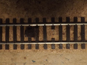
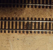
The photograph shows an uncoupler installed on ballasted track. When the replacement sleeper has been painted and the track ballasted the uncoupler becomes very inconspicuous. The acetate strip forming the uncoupling plate can barely be seen. The uncoupler is moved by a servo motor positioned under the baseboard.
Kit contents
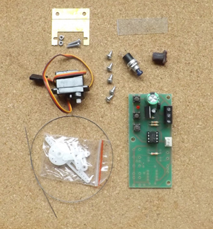
1 x servo motor, 1 x bracket, 1 x Uncoupler Servo Control board, 1 x piano wire, 1 x transparent acetate strip, 1 x push button switch, 1x 3D printed replacement sleeper and screws and nuts and bolts for the bracket.
Required are super glue and electrical wire.
The uncoupler is installed as follows:
Cut away the existing sleeper between the rails
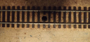
Drill an 8mm diameter hole in the centre of the space which was occupied by the cut away sleeper. Increased accuracy may be obtained by drilling a smaller pilot hole first.
Use the replacement sleeper as a guide to cutting away the existing sleeper.
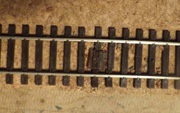
Glue the replacement sleeper in position. We used superglue.

Use self adhesive tape to cover holes in replacement sleeper then ballast track.
 Bend the piano wire to give a u shape which is 4mm wide. (a replacement sleeper not glued into the baseboard hole is shown for clarity)

Insert the u shaped wire into the two holes in the replacement sleeper then bend 90 degrees. (a replacement sleeper not glued into the baseboard hole is shown for clarity)

The u shaped wire is inserted into the holes in the replacement sleeper.
The acetate plate is glued onto the piano wire.

Mount the servo motor under the baseboard so that the centre hole on its crank arm lines up with one of the lengths of piano wire protruding under the baseboard.

Before fitting the Servo arm complete the wiring. Hold down the delay button until the Servo moves (explained later). One end of u shaped wire has been inserted into the Servo arm. The Uncoupler Control board can be seen. The lead from the Servo motor plugs into this board. The blue wire to the control board is negative power the orange is positive power and the white is connected to the push button switch.
Wiring and uncoupler height adjustments
 Wiring is simple. The Uncoupler Control board is connected to a power supply, regulated 12 Volts DC is preferable but the board will work from AC. The push button switch (push to make) is wired to the S terminal and to either the 0 terminal or the negative terminal of the power supply depending which is most convenient.
Switch the power on. Now hold down the delay push button on the Servo Uncoupler Control board. After about 5 seconds of being held down the servo motor arm will move. The servo motor arm is now in the middle of its range. (from this position the arm can move about 80 degrees clockwise or anti clockwise. Fit the servo arm onto the servo motor pointing about 10 degrees below the horizontal. With the uncoupling plate resting on the sleepers bend the nearest piece of piano wire so it passes through the hole in the servo arm. Now position two coupled wagons over the uncoupling plate. Press and hold down the pushbutton switch. By pressing button a and button b (shown in diagram on left) adjust the height of the uncoupling plate so that it rises high enough to uncouple the wagons without rising so much that it lifts their wheels off the rails. Release the control panel push button switch and wait for the ramp to lower which it will do after the delay time.
When uncoupling the train needs to be positioned over the uncoupler so that both coupling hooks can be raised by the uncoupler. Also the vehicles to be uncoupled must have slack in the couplings. Ie the engine may need to be reversed. If the couplings are tight then the hooks on them will be fixed beneath the bar of the adjacent coupling and the whole wagon will lift up when the uncoupler is operated regardless of what type of uncoupler is used. Our experience is that the train seems to nearly always stop with slack in the couplings.