Tel.
01538 756800
SA1.1 and SA1.1-S
The SA1.1 controls a shuttle line with one or more station stops. It has gradual and adjustable braking and an adjustable delay at the station stops. There is an option for sidings at one or both ends of the line to allow a number of trains to alternate along the shuttle. The diagram below shows some of the ways the SA1.1 may be used.
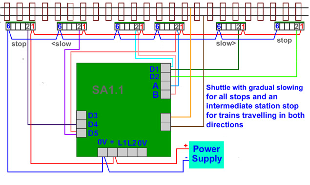
 The red arrows show the position of train detectors. Either IRDOT-1 or reed switches may be used for train detectors. D1, D2, D4, D5, A and B are terminals on the SA1.1. For trains travelling to the right the terminals make the following operations happen:
D1 train starts slowing gradually at an adjustable rate. The train will slow to a crawl (adjusted by the minimum speed pot).
Atrain stops waits for an adjustable time then restarts continuing to travel to the right
D2train stops waits an adjustable time then restarts travelling in the opposite direction (to the left)
Terminals D4 D5 and B are ignored by trains travelling towards the right. Whilst trains are travelling to the left terminals D1, A and D2 are ignored. When trains are travelling towards the left they do the following.
D5 train starts slowing gradually at an adjustable rate. The train will slow to a crawl.
B train stops waits for an adjustable time then restarts continuing to travel to the left.
D4train stops waits an adjustable time then restarts travelling in the opposite direction (to the right)
LED indications There is a red and green LED on the SA1.1 board they show the following actions are happening.
GREEN LED LIT = Train accelerating or travelling at maximum speed.
RED LED LIT = Train braking or stopped.
RED and GREEN LEDS flashing alternately = Adjustable Time Delay. The length of time of the delay is proportional to the duration of the flashes.
RED and GREEN LEDS both lit = Overload. IE short circuit on track.
Power supply
The SA boards are designed so that the control electronics and track power can be separated. This allows either the whole unit to be powered from a single AC or DC power supply; or the track power from a controller and the control electronics from a separate AC or DC power supply. No controller is required although one may be wired into the board to override the operation. Alternatively a DPDT switch could be used to switch between manual and automatic operation. See switchesfor more information about this.The reason for using a separate controller is to allow the train to be slowed or stopped manually and reversed for shunting. The maximum speed to be set by the controller setting. This option is of more use with other units such as the SA5 SA6 SA7 and SA8. Feedback controllers will not work with the SA units.
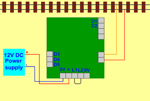
12 volt DC supply
 This option powers both the control electronics and track from a 12 volt DC power source. Put a link wire between terminals L1 aqnd L2 or leave the diode and capacitor in place. Connnect a 12 volt DC supply with positive to the "+" terminal and negative to the "o" terminal.. When first powered the train must move from left to right (move towards D1 and D2). If it moves in the other direction swop over the two wires to the track.
Using a smoothed regulated DC power supply will give pure DC at the track suitable for N gauge locomotives and coreless motors.
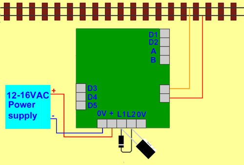
AC Supply

Replace the wire link with a diode, the band on the diode must face the direction shown in the diagram. The supply to the track with an AC supply will be unsmoothed DC. This may cause damage and overheating of N gauge locomotive motors but is satisfactory for OO gauge in fact older OO models may run better with unsmoothed DC. The DC on the track may be smoothed by using a (electrolytic) capacitor. The capacitor must be attached with its negative leg to the rightmost terminal. Using the capacitor will make the track power smooth and suitable for N gauge and coreless motors.
Train controller

Remove the link and connect as shown.
The automatic control only works with one direction setting of the controller the other direction setting will allow trains to be reversed manually. Feedback controllers will not work with the SA board.
Train detectors
The SA1.1 needs to know when the train has reached a slowing or stop position by train detectors located in these positions. Either IRDOT-1 or reed switch and magnet can be used to detect the trains.
IRDOT-1
These must use the same power supply as the SA1.1. Every terminal 6 connecting to "o" and every terminal 1 to "+".

Terminal 2 of the IRDOT-1connects to the appropriate terminal D1 D2 D4 D5 A or B. Refer to diagram at top of first page
Reed switch
One end of each reed switches is connected to the "o" terminal and the other end to the appropriate terminal of the SA1.1 ie D1 D2 D4 D5 A or B.
Location of train detectors
If IRDOT-1 are used then the stop train detectors are positioned where the leading ends of the trains stop. If reed switches are used there positioning must correspond to the position of the magnet on the train. Allow the same braking distance for every stop. For the intermediate station stops you will probably locate the stop detectors at each end of the station platform. It may then be possible to use the stop detector for right travelling trains as the slow detector for left travelling trains and vice versa, however if you want a different braking distance you can use separate slow detectors. The SA1.1 will work without any slow detectors at all.
Set up adjustments for the SA1.1

There are adjustments on the board for maximum speed, minimum speed delay time and rate of acceleration/braking. The train will accelerate to the maximum speed setting and brake to the minimum speed setting. The minimum speed is set to the slowest speed the train will reliably travel at.The idea being that this is more certain than slowing the train to a complete stop by the acceleration control alone as there would then be the possibility that as the engine warms up or an extra coach is added the stopping position might be affected.
Overload protection
Overload protection is built in to the SA1.1. If a short circuit occurs on the track due to a train derailing etc then the unit switches off power to the track and lights both the red and green LEDs. Power is restored once the fault is removed. The overload protection is triggered when the current to the track rises above 1 amp.
Gauges and scales
They are suitable for all analogue N and OO gauge engines. All the SA boards can be used with Z gauge provided a regulated 12 Volts DC power supply is used to power the board and Heathcote Electronics makes a small modification. This is to ensure the output voltage is 9 volts or less so that the locomotive's motors are not damaged. Modern O gauge locomotives work fine as they have efficent electric motors, small LGB engines also work fine. With larger LGB locomotives or old O gauge ones check that the current consumption is not more than 1 amp. If it is we can custom build boards to supply much higher currents.
G scale Funicular
The video shows a G scale Funicular railway. The pulley wheel at the top us rotated by an electric motor under the base board. The SA1.1 controls this motor. However the left hand coach has a magnet underneath and this activates slowing and stop reed switches along the left hand line. Although the carriages are quite heavy the string linking them via the pulley wheel balances the 2 cars so very little effort is required to move them compared to pulling a single car up the slope.
Sidings at one or both ends of the line
It is possible to add one or more sidings at one or both ends of the line. This will allow one train to arrive and another depart. If you were to have for example one point at the left and two points at the right you would have 5 dead end tracks. This would be able to contain four alternating trains as you need one empty track for a train to arrive in. An IRDOT-P is required at the end of each siding. This both changes the point (operated by peco hornby seep point motors) and replaces the train detector at the end of the line. A single slow down train detector can be positioned before the lines divide.
The IRDOT-Ps serve two purposes. They have contacts to switch the points and a terminal (P) that connects to the SA1.1 to indicate that a train has arrived. Unlike the IRDOT-1 whos terminal 2 is activated all the time a train is over it, the P terminal of the IRDOT-P gives a shortpulse when the train arrives, this allows all the IRDOT-P terminals at one end of the line to be wired together and connected for example to terminal D2 or D4 and still recognise athe arrival of a new train despite trains standing over other IRDOT-Ps.
The wiring can be checked before the point motor is wired up by ensuring a single train starting at the left shuttles backwards and forwards.
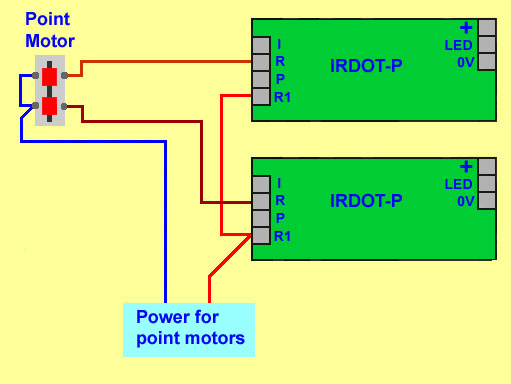
The IRDOT-P "R" terminals close momentarily when a train arrives over the IRDOT-P. Wire the point motors to the "R" terminals so that an arriving train causes its point to change ready for the next train to depart after the wait time. Depending upon the number of sidings more than one point may need to change.

This diagram shows how the two IRDOT-P are wired to operate the point motor. A CDU could be used for the power supply. One terminal of the power supply connects to the common of the point motor. The other connects to both R1 terminals. When the IRDOT-P detects a train its internal contacts will momentarily connect R to R1 so energising the point motor. An arriving train should cause the point motor to set the point to the other line. If this does not happen swop over the wires to the R terminals.
Dimensions
114mm x 104mm
Voltage
12 to 16 Volts AC or DC
SA1.1-S
Apart from the signals the operation of the SA1.1-S is identical to the SA1.1-S. The SA1.1-S can control a total of 4 signals two signals for the terminus and a signal for each direction at the intermediate station. If their is more than one intermediate station this does not work correctly as the signals for the intermediate station will change regardless of which station the train stops at. The signal controls consist of changeover contacts isolated from the rest of the electronicson the Sa1.1-S. The operation is for the signal to change to clear just before the train departs and return to danger a few seconds later or when the train reaches the next braking detector. The SA1.1-S is more difficult to use with sidings at the end of the line.