Tel. 01538 756800
How infra red train detection works

Our eyes only see a limited range of colours. Some animals see a wider range than we do. Infrared is the colour before red in the spectrum and it is invisible to us but behaves in the same way as visible light. Some phone cameras can be switched to see infrared.
Our system of train detection works by shining a beam of infrared upwards from the track. If anything is above the beam it will reflect some of the infrared back. When our boards see this reflected infrared they know rolling stock is above.
The electronic circuit board filters out background infrared and electrical noise.
Extending 22mm from our boards are an infrared emitter and an infrared detector, these emit and detect the infra red. Both emitter and detector are the size of a 3mm diameter LED. They fit between and level with the bottom of the sleepers. Operation is not noticeably affected by the sleepers partially obscuring the infrared devices and even with Z gauge they work satisfactorily with the standard sleeper spacing. The detection range depends upon the colour and reflectivity of the object above but is typically 40mm (1 1/2 inches).
Where it is difficult to fit the detector due to baseboards thicker than 22mm or cross beams under the baseboard the units can be supplied with the infrared emitter and detector connected to the board with wires. These boards are distinguished from standard ones by having EW added on the end (EW stands for Extended Wire).
A glossy white surface reflects more infrared than a matt black surface and so the glossy white surface will be detected from a greater distance. Although rolling stock has a matt black underside it is usually detected without any problems. If detection is erratic a white self adhesive paper label or similar can be fastened to the underside. Tunnel ceilings above detectors may need painting matt black if they are a light colour to prevent them being detected. All materials reflect infrared in varying amounts. Rolling stock of any colour, constructed of plastic, metal or card is detected.
The sensitivity can also be adjusted by allowing more or less infrared be emmitted. Heat shrink tubing covers the emitter and detector. Its purpose is to prevent the infrared going sideways from emitter to detector. If this is trimmed back more infrared will be emitted and the range increased. However be careful not to expose both emitter and detector as the infrared will then travel sideways making the detector think it is permantly detecting a train. If longer pieces are shrunk over the top the range will be reduced.
Normally none of these measures are required and the units work satisfactorily as supplied.
As the infrared is supplied by the units themselves infrared detection works equally well in light and in dark.
The diagram shows the IRDOT-1 fixed to the underside of the baseboard. The tips of the emitter and sensor are positioned level with the bottom of the sleepers.
The two photos below show the two sides of the IRDOT -1.
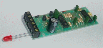
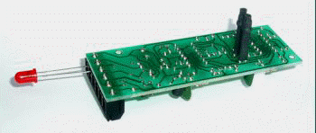
The left hand image shows the component side of the IRDOT-1. The LED is shown in the position as supplied before being wired to the control panel. The right hand image shows the detection side of the IRDOT-1. This side is fixed to the underside of the baseboard. The two vertical projections are the infrared emitter and detector which fit into a predrilled hole in the baseboard. When correctly located the tip of the detection device is level with the bottom of the sleeper.
Advantages of Infra-Red detection
Infrared train detection has the following advantages. The units detect all rolling stock in a train. This is particularly useful when trains such as DMU's run in reverse. The infrared detectors are inconspicuous and are usually fitted with the circuit board under the baseboard.They are simple to install and can be fitted to existing track. No modifications are necessary to the track wiring or the rolling stock. They are electrically separate from the track, making wiring simple. They work in both the light and the dark. The detectors are suitable for Z, N, HO, OO and O gauge.
Power supply
All our modules can be powered from 12 to 16 Volts AC or DC. We stock a suitable 12 Volts DC supply alternatively a controller accessory output is a suitable power source. The low power consumption of the units (less than 20ma for the IRDOT-1) allows many modules to be powered from the same supply.
Installation of Infra-red detection modules
Units with built in infrared detection are designed to be screwed to the underside of the baseboard with the infrared emitter and detector located in a hole between sleepers. See diagram at the top of the page. It is easiest to install the units after the track is laid. Drill a small pilot hole between the sleepers. Fit an 8mm drill bit marked with tape for slightly less than the base board thickness. Drill from underneath the baseboard following the pilot hole. Cut or file the small amount of baseboard material left between the sleepers. Install the unit and then fill the remainder of the hole with modelling material. Blu-Tack will hold the units in place temporarily. Use 1.2mm holes for the self-tapping screws that hold the units permanently in place. When fitted to Z or N gauge track the gap between sleepers will be less than the diameter of the infrared detector and emitter. However, the modules work well provided they are adjusted to fit close to the sleepers. This positioning prevents reflections off the sleepers causing detection. For base boards thicker than 22mm (i.e. the height of the infrared devices), or where there are obstructions, the units can be supplied with the infrared emitter and detector fitted to extended wires up to 400mm / 18 inches long. They can also operate on their sides.
Blocked beam detection
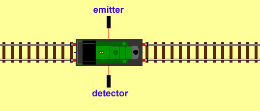
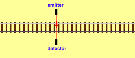
Where it is difficult or inconvenient to fit the detectors under the track to work by reflection an alternative is to use the EW (extended wire) version and shine a beam of infra red across one or more tracks.
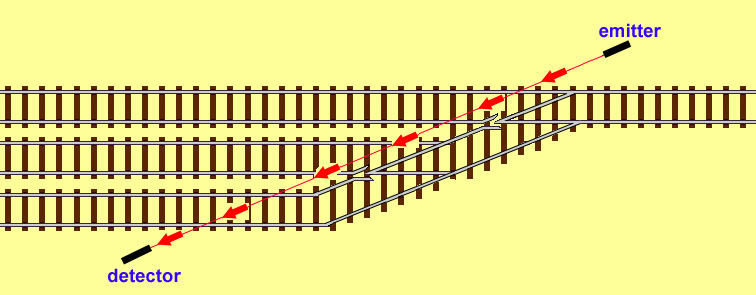
Reversed operation
When the boards are used with a continuous beam the operation is reversed. With no train present infra red is sensed by the detector and with a train present no infra red is received by the emitter. This is the opposite to what happens when the infra red detector is working by reflected infra red. For example if you used an IRDOT-1EW the occupied LED would light when no train is present and the unoccupied light when the train was present. This is not really a problem as you could swap over the red and green LEDs, however it is a problem when you link the IRDOT-1EW to an SA1 for example as terminal 2 of the IRDOT-1EW tells the SA1 the train is at the detector when it is not. To overcome this we have the IRDOT-1EWBB (blocked beam) which will operate with an SA1 etc when used for detection with a broken beam.
Reflection above the baseboard

It is possible to use the emitter and detector side by side above the baseboard but this has some snags. Inside a tunnel for example you may detect the opposite side of the tunnel, so the detector will then show continual detection, you may also detect a train on a parallal track. However it is very successfull for locating trains inside engine sheds.
Types of unit
The infrared emitter and detector unit is built into many of our circuit boards including IRDOTs (InfraRed Detection Of Trains), IRDASCs (InfraRed Detection And Signal Control), MAS-Sequencer (Multiple Aspect Signalling), the Simple Shuttle, etc.We manufacture the following Infrared Units:
The basic unit. This lights a (control panel) LED. It has an electronic train detected switch to activate our other units or operate a second green not detected LED. It is also possible to operate a bicolour LED to give for example green not occupied, red occupied. The switch may also operate a relay or opto-isolator for interfacing to a computer etc.
Main Uses:
Train detection and indication of trains in fiddleyards, hidden sidings, inside stations with overall roofs, engine sheds etc.
Train detection for our SA range of shuttles, passing loops, station stops, block sections etc. The advantages over reed switches are that no magnets need to be fitted to the engine and the detector can be positioned where the front of the train is meant to stop rather than where the train mounted magnet will finish.
Train detection for uncouplers. When uncoupling at a distance from the controller it is difficult to judge when the couplings are aligned over the uncoupling magnet. The gaps between the vehicles can be detected by positioning the IRDOT-1 between the sleepers on the outside of the rails, these sleepers being adjacent to the magnet fitted within the rails.
Terminals are identical to the IRDOT-1. Operation is the same as the IRDOT-1 except it detects the train immediately but has a 4 second delay before indicating the train has left.
Main Uses:
The same as the IRDOT-1.
It provides continuous detection of a train. Unlike an IRDOT-1 where the gaps between wagons cause the LED to flicker, the IRDOT-1D's LED will remain lit during these gaps due to the 4 second delay.
The constant output can simplify the design of computer software and home made signalling and control systems.
IRDOT-1AD
This works like the IRDOT-1D but has an adjustable delay. The delay is selectable from 3 to 24 seconds in 3 second steps.
This operates an LED and built-in changeover contacts. The contacts are electrically separate from the IRDOT-2's power.
Main Uses:
Automatic isolation of trains in storage sidings.
Replacement for reed switches.
The contacts provide electrical isolation to enable interfacing to computers, programmable logic controllers, etc. As well as detecting trains they have been used as proximity detectors for movement of model crane arms, turntables etc.
This has the same outputs as the IRDOT-2, but also has a 4 second delay to prevent the LED flickering and the contacts repeatedly switching as the train travels over it.
Main Uses:
System of moving up trains in storage sidings.
Operation of lineside accessories as the train passes.
Providing indication of train position to computers, programmable logic controllers, etc where a single pulse is required for the whole train.
This has double pole changeover contacts and will operate either detected and undetected LED's or a bicolour LED. The bicolour LED changes colour from green for no train detected to red when a train is detected.
Main Uses:
The same as the IRDOT-2 where a bicolour display or double pole contacts are required.
The first set of relay contacts can be used for automatic stopping, the second set for interfacing with a computer or completely seperate electrical circuit..
This has the features of the IRDOT-3 with the addition of the following selectable delays: 3, 6, 9, 12, 15, 18, 21, and 24 seconds. These are selectable by connections to the terminal block.
Main Uses:
The same as the IRDOT-2D where a bicolour display is required.
The delay can be used to isolate a crossing line to prevent collisions.
The delay can be used as a switch for level crossing lights.
Simple 2 aspect signalling. The unit is placed ahead of the signal and timing is selected to be long enough to keep the signal at green until the train has passed.
Useful for use with "brake on DC" for gradual slowing of DCC trains.
Changing polarity on DCC reverse loops.
The following units use infrared detection to control signals and points
This operates solenoid (PECO SEEP HORNBY etc) point motors on detecting a train. It also has a train detected LED. These units can be used to operate automatic reverse loops and storage sidings.
This operates a 2, 3 or 4 aspect signal on an adjustable time system. A feature is its very simple wiring.
These units operate 2,3 or 4 aspect signals. The signal aspect depends upon the aspect of the next signal or the presence of a train in the next section. The unit may either follow a MAS-Sequencer or be part of a chain of IRDASC-4 units.
Works as IRDASC-4 with addition of control for a route indicator/feather.
This works as described for the IRDASC-4 with the addition of contacts to provide track isolation for stopping trains when the signal is at red.
This works as described for the IRDASC-4 with the addition of contacts to provide track isolation when the signal is at red and control for a route indicator/feather.
These operate 2 aspect common negative LED signals. The signal is normally at red until a train approaches. Provides sophisticated control with interlocking to points and the next block sections.
These units can operate 2 aspect bulb or LED colour signals. They can control semaphore signals where they are actuated by servos and servo controllers, slow motion point motors or memory (muscle) wire. The signal is normally at danger until the train approaches. Provides sophisticated control with interlocking to points and the next block sections.
These units operate as described for the IRDASC 2 but have contacts which may be wired to isolate a section of track before the signal when the signal is at danger..
These units operate Dapol semaphore signals. The signal is normally at danger until the train approaches. Provides sophisticated control with interlocking to points and the next block sections.
These units operate Dapol semaphore signals on an adjustable timing basis. The signal is at danger until the train is detected approaching the signal. Once the train is clear of the detector the signal returns to danger at the end of the adjustable timing period. Designed for simple wiring.
The following 2 units are for automating trains.
The train is stopped upon being detected by the Simple Station Stop. After an adjustable time the train departs. There is an option for a 2 aspect platform signal to be operated.
The Simple Shuttle is used to automatically run a train backwards and forwards along a branchline. It is located at one end of a branchline and used in conjunction with an IRDOT-1 located to detect when the train has reached the other end. There is an adjustable timed stop at each end. Sidings may be added at one end to allow alternate trains to run. Sidings require IRDOT-Ps to be used to control the points.
The following units are for blocked beam detection
IRDOT-1EWBB
IRDOT-1ADEWBB
IRDOT-3DEWBB